fb icon

fb icon
Follow E-tek on fb!

November 8, 2012

More Wiring, Seats, Dash vents


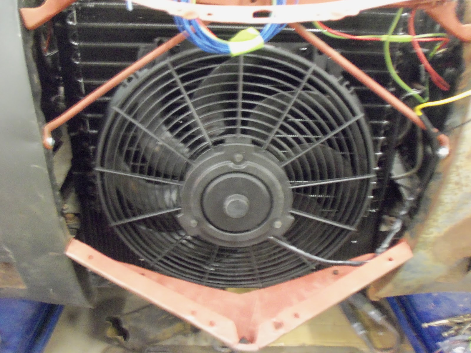
Finalized the fan wiring on the 40 Ford with a 40Amp relay:


Mounted other engine relays to the inner fender:


Wired up the water temp and alternator leads:


Put it all in wire looms, then bolted the front end back together:


 Inside, I re-arranged the pedals as per owners request (surprise!)


Then removed the seats in order to fabricate some mounting tabs so they could be bolted in:


The seats supplied had these tabs in front that clipped into holes in the original vehicle:


Which needed to be removed and some feet welded on in their place that could be bolted down.
I turned the seats over on a stool and taped cardboard down in order to protect the seats from burns:


Off came the tabs:


New feet cut and drilled:


Then welded onto the seat bottoms:


I then turned the seats over and welded the tabs from the top-side. We don't need them coming apart!


The seats were re-positioned, holes drilled in the floor panel and then they were bolted in using spacers to get them leveled out. I used pieces of wood for now, but will try to source something else for a permanent solution.


 These side vents are supposedly made to fit these holes in the 40 Ford dash. They don't fit very well no matter which way I inserted them....


I'll have to either re-work the edges to even them out, or find some type of bezel that could fill in the gaps...


Tomorrow we'll be able to put the dash in loosely in order to begin the initial mock up of the console. Lots of "big changes" coming up!


Don't forget to check out my website at 
www.E-tekRestorations.com!

November 4, 2012


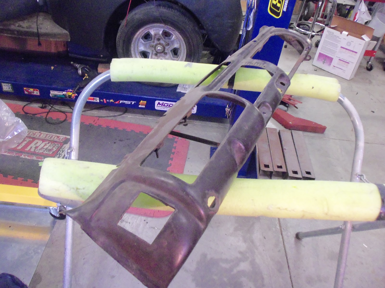
Here's the original dash - in very good shape!


Glove box opening needed a bit of tweaking to get the door to fit straight:


Simply bolts up from the back - no plastic tabs, grommets or snaps!


Modern gauges look great in it:


 this old clock was in the box but I don't think it's from this car. Just thought it looked cool.


Radiator, then front nose pieces went on. It's a tight fit due to the narrowing style.


Tight fit with the engine not set back. Many 40 Fords have the firewall cut in order to set the engine further back. This one was dropped right in the cross member.


Rad inlet will likely have to be moved top the center, which will like up directly with the engine thermostat housing:


The tranny cooler lines come close to lining up. I'll get the rad and AC shop to put their touch on these when they do the rest of the fittings. 


Wired in the headlights and ran the fan wire from the aftermarket harness:


I like to use unique fasteners in my builds. Purchased these SS #3 Robertson headed screws to put this rod together. Of course they can always be changed out after paint.


A Hayden Rapid-Cool pusher fan was purchased and installed with a 40A relay:


The front end is coming along now. Just gotta keep the wiring organized!


Don't forget to check out my website at 
www.E-tekRestorations.com !

November 3, 2012

Sometimes it helps with planning by thinking out loud, or writing stuff down. With a lot of the background wiring done on the 40 Ford, as well as some of the systems like power windows, locks and latches, as well as the AC and heating systems mocked up, I can get to some of the stuff that actually makes the car LOOK different!

On the front end, the rad and fan will go in next. As the tranny fluid lines are too heavy to bend by hand we`ll likely have to wait to make the final tranny cooling connections along with the AC system. By working around that, I`ll be able to get the rad, fan and relay bolted in and set up, as well as pre-fit the front end, hood and grille pieces.

The dash panel will first go on a rack so I can pre-fit the gauge cluster plate, AC side vents, glove box door and other details. Once everything is done I`ll put it in the car for another stint as I work towards the console fabrication. The gauges will be hooked up with a MOLEX style connector for easy in and outs and servicing.

Once the seats are in their final positions I`ll drill mounting points and use Grade 8 hardware to fasten then down, The front mounts have a slip-in design but I`ll likely weld on a tab for a through- bolt. Wood spacers will be used to level the seats up until I can find something more suitable, like ABS block.

With the seats and dash in place I can then begin the mock up the center console. For strep I I have sheets of Bristol board to cut up and tape together, Once it`s close I`ll use the pattern to cut some sides out of thin wood sheet then work with the owner to determine the style for the top side.

Working back around the rear, I`ll wire up the lights, fuel pump relays and the battery. No  point having the battery in place until all the major components and wiring is done, but at this point we`ll be able to start hooking stuff up and testing circuits.

The only bad plan - is the absence of a plan. :)


Don't forget to check out my website at www.E-tekRestorations.com !

November 2, 2012

LOTS done today!


Time to tackle the front end wiring....


 First I separated everything into lights, engine sensors and power runs...

I cut out a lot of the excess wire and re-routed it all to the end pieces.
 Then I tore apart the old harness and took out the parts I needed: lights, alternator, starter wires, etc:
 Here you can see the light connectors wired in just awaiting new hi-low sealed beams.
 This is the electric wiper controller, ready to be set in the console with everything else.


I stopped there on the wiring for now, as I needed to get some of the front end together to check the rad placement, fan size, routing for the wires, etc. I also need to buy some stuff for this next week of work, including components to build the console and Hi-low headlights.


 Having the computer in the shop sure makes finding wiring diagrams and advice on engine swaps easy!
 You'd think by now manufacturers would have come up with something not so delicate to wick heat away from the coolant!

Every time I unwrap or work on a rad, some fins are bent, crushed or worse - this one is brand new, it's just been moved a few times.
They sell fin "combs" to straighten bent fins - and I used to have one - somewhere. A screwdriver works too...


I straightened out most of the worst offenders, then removed the tranny cooler and turned it around to meet up with the lines coming from the car. I'm guessing it was ordered for side lines, they just put them on the wrong side!

After measuring it up I added an 18" electric fan and some tranny line connectors to the shopping list.


I then spent some time mocking up the seat placement (the yellow Bristol Board is to mock up the console later):

The owner made a good choice on the seats. They're in great shape and both flip and slide forward for easy access to the back seat. The drivers seat is powered as well, which was wired up yesterday.

The floors is rather uneven so I made sure the car was level on the lift and that the seats remained level as I moved them around.


On the drivers seat, the outside rail will be raised about 1.5" and the inside rail only 1/2". On the passenger side only the outer rail will be raised 1/2".


Key parameters in locating the also include sight lines out the glass, shoulder height, as well as how close it comes to the shifter, steering wheel and pedals.


Although a ton of work has been done it doesn't look much different - but it'll sure work different!


November 1, 2012


 Finalized the Vintage Air system today, including routing all the hoses and wiring. Its a BIG system for sure. This is the heater control valve, which allows hot water to flow into the car when the heater is turned on. The cut you can see in the heater hose is where I had to put part of the metal tube (that I removed from under the intake plenum) back in, in order to keep the small tube in play, which siphons off coolant (hot water) to the throttle body (TB). This keeps the TB and itès sensors at temperature.


Heres that piece installed. Unfortunately, I like things to look clean and it makes for a lot of clamps...


Just below that I brought the vacuum and 12V lines out to be connected to the battery source at the solenoid.


Below Im hooking up power to the drivers seat. Gonna be a well-appointed rod!


The wiring harness from Its a Snap came with only 3 connectors pre-set and one was for the high-low dimmer switch on a GM column!


Sometimes hoses that fit one end are really tight at the other end. In these cases I often use a heat gun to soften the hose and WD-40 to help it slide over the connecting tube.


Don't forget to check out my website at 
www.E-tekRestorations.com !