fb icon

fb icon
Follow E-tek on fb!

October 6, 2012

Fabricating working peices


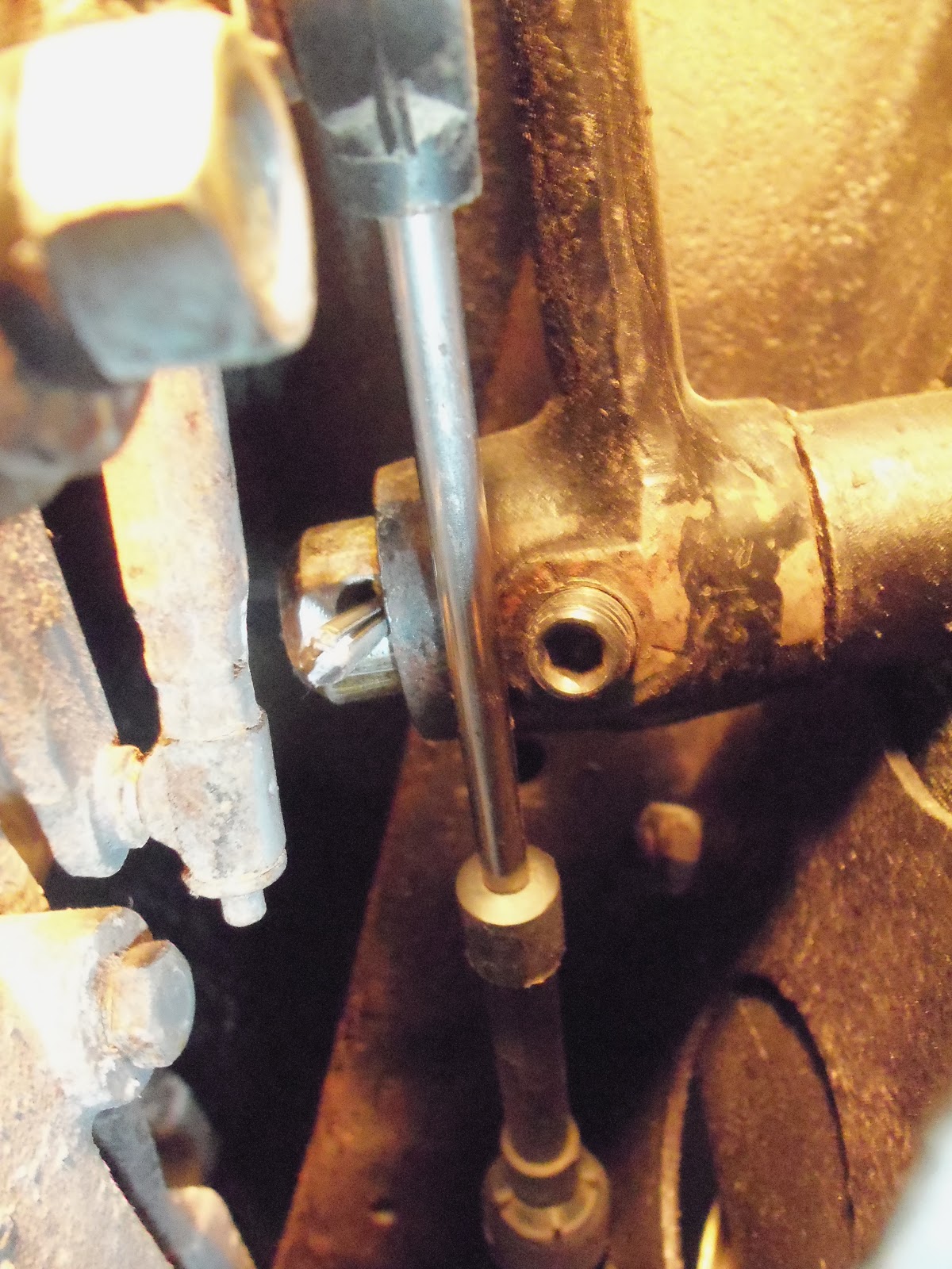
One thing I always do when re-using bolts in a restoration is chase the threads. In putting the AC brackets back together for the 4th (but likely not the last) time, I cleaned up the bolts that will go into the block and pump, as well as the threaded ports in the block where it all mounts to.


I needed a specific shim to get the tensioner lined up just right, so I just made one out of some 3/8" stock by drilling a couple holes in the right spots, then cutting them into slots:


The finished product:


The tensioner pivots at the top bolt and slides along the slot in the bracket to adjust tension on the belt.


I had the power steering hose cut down and rebuilt at Greenline Automotive last week and just got to installing it. When I put it in the first time I realized it was going to interfere with the oil filter, making it real tough to change it during routine maintenance. So I flipped it over and mounted it with the hose facing forward. This gives us back the room to unscrew the oil filter - but now it rests against the upper control arm. Gonna have to think on that one for a spell - I wouldn't want the repeated contact from the suspension movement to cause an issue with it.....


Next up was the brake pedal assembly:


First up was to determine where everything was going to sit when the pedal was at rest and then fully depressed. We're using the original pedal shaft as it has the correct bits on the bottom end, so I had to find a nut that would fit the custom pedal that I could weld to the shaft:


Lots of checking pedal travel was key to the entire operation...


Under the vehicle, I mocked up the shaft, lever and pin, making sure the master cylinder rod would move all the way in and out and not bind up.


Once satisfied, I temporarily tacked the leg to the shaft.


With everything working, I took it all apart and fixed up the shaft so the pedal shaft would stay put when depressed. For this I put a flat spot where the set-screw would make contact. I also drilled a hole for a cotter pin to ensure this shaft couldn't go anywhere again!


The nearly finished piece:

Back under the car, I greased it, slid it through the mount and bolted it to the clevis. This bolt will get some Loctite before we call it done.


Looking at the other end you can see the set-screw on the bottom of the brake pedal. The first time I tightened the set-screw and depressed the pedal nothing happened. After some head-scratching I found that the set screw was binding in it's threads, so it would feel like it was tightening against the shaft, but really wasn't. That would be what happened to the first shaft! I removed it once again and ran a tap though the pedal, cleaning up some thread near the deep end and then the set screw went all the way to make contact with the shaft.


Then after welding that castle nut onto the shaft, I bolted the pedal on. Looks a little odd at this angle, but it seems good from inside. I also left the pedal high so as to err on the side of caution. Once we test the braking system and decide on a final spot, we can easily move it to suit the owner.


Looking under the dash, the EEC computer is mounted to the firewall and the E-brake lever (original) was mounted as well.


As the battery is being located in the trunk, I ran 4 gauge wire along the rail, separating it from the fuel line with rubber lined frame clamps.


...and here's the lug terminated at the solenoid:


MEANWHILE,, back at the farm....

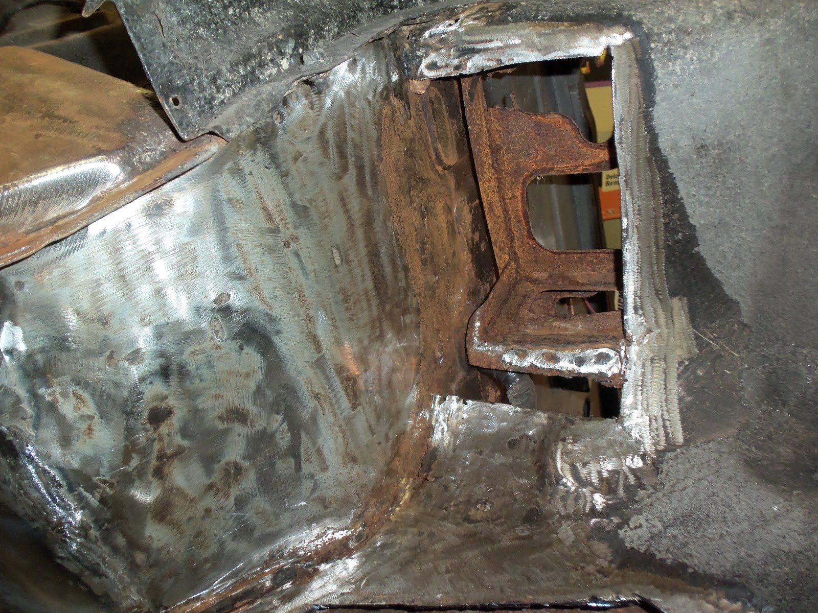
After 4 hours on the Rod, I decided to keep the 240Z in play by doing a little bit on it as well. Under the battery tray is a rot-spot for all these vehicles. New metal on it's way!


As per my MO, I sprayed MetalReady on all the surface rust to stop it dead.


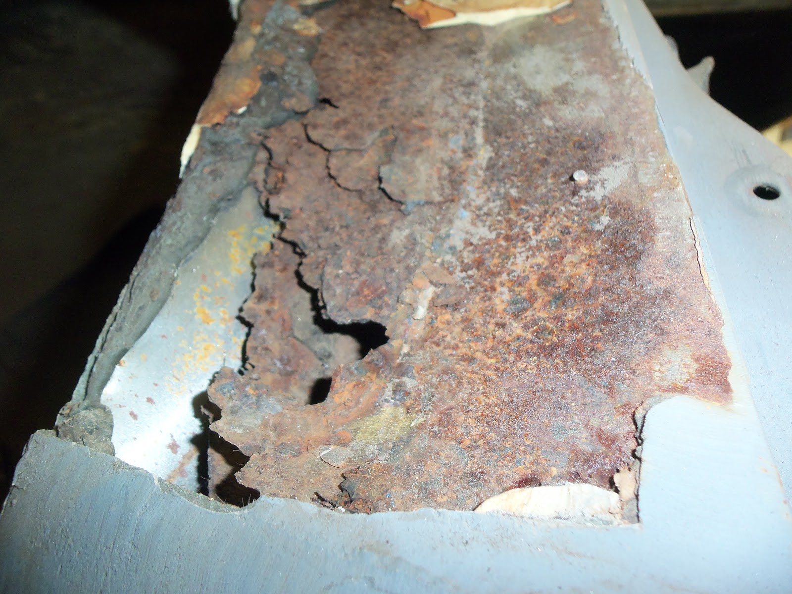
Looking ahead a bit, here's what lies in wait under a fiberglass quarter panel....


 Here's where you can run that horror-movie music in your head: Dun-Dun-Dun-Dun.....


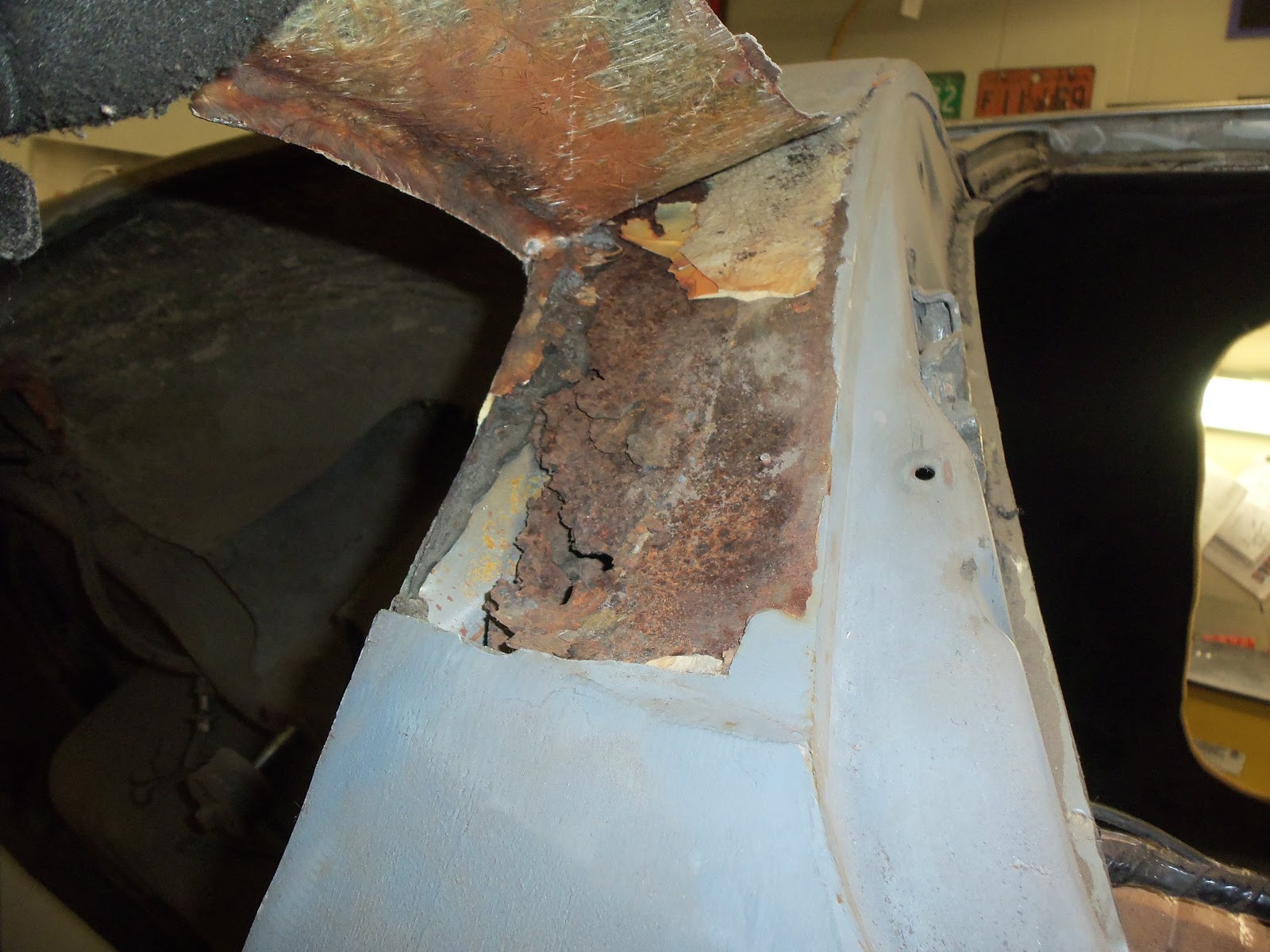
Cue screams of horror!!!!!
Yikes! Looks like a lot of work....but just think what it'll look like with NEW metal!

Don't forget to check out my website at www.E-tekRestorations.com !

October 5, 2012

Long weekends RULE!

Ah the long weekend.....time to get stuff done!  Unfortunately a giant hunk of our big crab-apple tree broke off earlier in the week so I had to start Day 1 cleaning that up with the chainsaw (arrgh!).

Luck for me (?) I had the "help" of my 2  kids....  So after getting that all cleaned up I was ready to get into the shop as the temps around these parts had dropped to near freezing in a week! Alas, when I got into the shop and tried to fire up the big heater.... I got nothing but a blast of cold air down my back - just like the times when I inadvertently say the wrong thing to Mrs E-tek..

Anyways, with a sore back in a cold shop, I still managed to get a few things accomplished on the 40 Ford Rod while waiting for a furnace repairman to come look at my REZNOR.

You'll recall the template I had started on to mount the tensioner for the AC pump side of the serp-belt system:


After transferring the shape onto some 1/8" plate, I cut a rough shape with my Makita 4 1/2" angle grinder:


Next up was drilling the required mounting holes, as well as holes to make the slot for the tensioners swing-bolt to ride in. To get the slot located correctly, I mounted the top pivot bolt, then scribed the arc with a bent dental pick. I then drilled 3/16" holes along the arc's center-line, then re-drilled every second hole with a 7/16" drill. Once all the holes where drilled, I cleaned it all up with a die grinder, then finished it by hand with half-round and round files.


Test fitting the slot:


Once I was satisfied, I smoothed the edges, sanded it down and sprayed some fast-etch primer on it.


Next up was the brake pedal. Earlier I had done the skinny pedal and cable set-up and when doing so I noticed the original brake pedal dangling from the floor board. Apparently there was a rod that went though the after-market booster/master cylinder set-up to locate the pedal, but it had disappeared somewhere along the line.

Interestingly, I was at my local metal recyclers Thursday (man I love that place!) and picked up various lengths and diameters of rods and bolts, along with some other interesting items. This task required a 0.800" rod to go through the pivot housing to attach the pedal on one side and the master cylinder's push rod on the other. Oneof the pieces I scrounged was an exact fit (did I mention how much I love that place?) :)

First up was to cut the rod stock to length - note the cadmium coating....


 Then, I cut another piece from the same 1/8" stock as the tensioner bracket and drilled a couple holes in it  to give me a crude starting point. The small hole is to attach it to the rod joint and I also cut a larger hole at the other end, which I then cut in half to give me an area that would "wrap around" the rod for maximum welding surface contact.


After a little shaping with the grinder....


...and it'll be attached to one end of the rod like this. The other end will have a flat-spot ground into it for the brake pedal's set screw to bottom on. The housing it inserts into has a grease nipple to keep it all moving smoothly.


As I was finishing up these pieces the furnace was coaxed back to life (by my next best friend, Jason, from Entrust Heating), giving the shop some much-needed warmth, which aslo allowed me to put some paint on these items so that tomorrow I can get right to their installation! For those interested, the heating issue was nothing more than a blocked tube leading from the pressure valve to the intake fan....still, not my area of expertise so I was almost happy to part with some cash to get the heat back on!


Don't forget to check out my website at 
www.E-tekRestorations.com !

September 28, 2012

1940 Ford Rod: dems da brakes


Got the rear brakes sorted out and ran the e-brake cables to their respective locations in order to meet up with the e-brake handle and cable up front.


 The undersides of the Rod are in excellent shape, all of the metal having been restored  some time ago.


Locating an e-brake cable clip in the floor pan -


Up front I opened up a hole for the forward e-cable, then put a pry-bar in it and bend the frame wall such that the cable would go in at an angle where it would more easily run along the rail.


Next up was installing the gas pedal and then installing the LOKAR throttle cable system
.

With the pedal mounted in a spot that allowed full travel, I then attached it to the throttle cable end -


then cut both the outer sheath and inner cable and  attached it all to the throttle body linkage up front.


An issue we need to deal with is the angle that the steering linkages are at.  As can be seen below, the column is currently mounted so that the lower-most knuckles are at too-severe an angle, which could lead to binding. There's two possible fixes for this: try to find some block-hugger style headers so that the linkages could be moved inwards reducing the connection angle or, move the lower end of the steering column further outboard thus bringing it more in-line with the steering box.


 Stay tuned to see how it turns out!


Check back weekly for lots of updates!


       Don't forget to check out the website at 
www.E-tekRestorations.com !